
STOLSPEED VORTEX GENERATORS
Overview
| This is a really good way to demonstrate the difference that VGs make to the airflow. Notice that outer portion of the wing, behind the VGs, doesn’t stall at all, and the airflow remains attached and smooth. Notice that the inner portion of the wing, without VGs, stalls suddenly and the disruption immediately spreads over the whole portion. But note that the disruption doesn’t spread to the portion of the wing behind the VGs.Vortex generators (VGs) are well-proven for better low-speed handling, softening the stall characteristics, and lowering the stall speed, which makes it easier to do slower, gentler landings. Stolspeed VGs are streamlined for less drag and better appearance than other VGs. Stolspeed VGs have no sharp points and are flexible, so it’s easier to wash or cover the wings. The special 3M adhesive is removable without damaging aircraft paint.
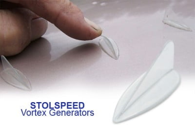
Advantages Stolspeed VGs Stolspeed VGs have a very slim rounded fin to give them good flexibility, and a rounded, tapered base that ‘flows’ into the wing surface. They really do look like they’re meant to be a part of the wing rather than a ‘stick-on’. In clear material they’re almost invisible. Brush your hand over Stolspeed VGs and you can feel the flexibility. |
Installation
Installing Stolspeed Vortex Generators
Flight Testing
It’s essential to do proper flight testing before and after installing any VGs.
Record the results, don’t depend on memory! Not only will you be able to measure the differences, but you’ll learn a whole lot about the handling of your aircraft.
Preferably select a time when the weather is looking stable for a couple of days (ie- a large high pressure cell spreading over your area). Do the first flight tests without VGs early one morning, install the VGs during the day, and flight test again with VGs early next morning when conditions will be consistent.
Instructions for the flight testing procedure are at Fight Testing.
CofG
It’s also essential to establish that the CofG of your aircraft is correct before installing VGs. And here we’re talking about the actual loaded CofG as it is for flight right now, not just the empty aircraft, or calculations way back when it was built. I keep running across aircraft owners seeking to use VGs to correct defects in handling which are really due to CofG problems – some due to additions over time – some obviously could never have passed a proper weight and balance at any time! (Auto engines need special attention…)
It’s a trap, that most aircraft will fly fine under power even if the CofG is way out, but lose that power and reality bites – either can’t get the nose up for a landing flare, or even worse, can’t get the nose down in a stall …….
I know that very few aircraft owners ever do a weight and balance other than when it was built, but it sure is worthwhile exercise – now is a good time to do it!
Instructions for Installing Stolspeed VGs on your aircraft.
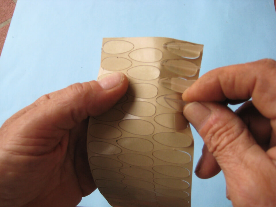
First it’ll be necessary to apply the special adhesive to the VGs.This adhesive comes as a thin sheet in a sandwich between two backings. It’s a solvent-free, acrylic adhesive that won’t damage any paint surface. Once firmly pressed onto a clean surface it bonds really well, but still has flexibility. Sudden impacts will not knock it loose, but it can be peeled away by pulling steadily on the VG and sliding a razor blade under. To remove any remaining adhesive from the surface, just rub with your thumb and ‘roll’ it away in a little rubbery ball. It’s a perfect adhesive for this purpose!
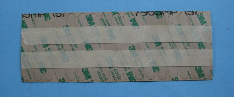
The sheets of adhesive now come already laser cut to the footprint of each VG. The laser often cuts through the backing of the adhesive as well, so to keep all the parts stable, place a couple of runs of masking tape across the backing (the printed side), as shown below.
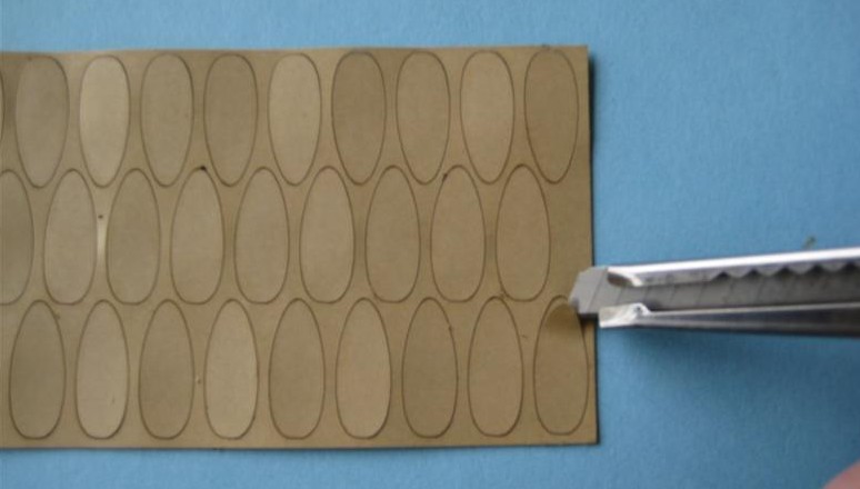
There may be kits out there, sent out before the pre-cut adhesive was available. In that case you can cut out the adhesive manually as below, or email [email protected] with your mailing address, and pre-cut adhesive will be supplied at no cost.
With a sharp trimming knife, slice the adhesive sheets lengthwise into 25mm (1in.) wide strips.
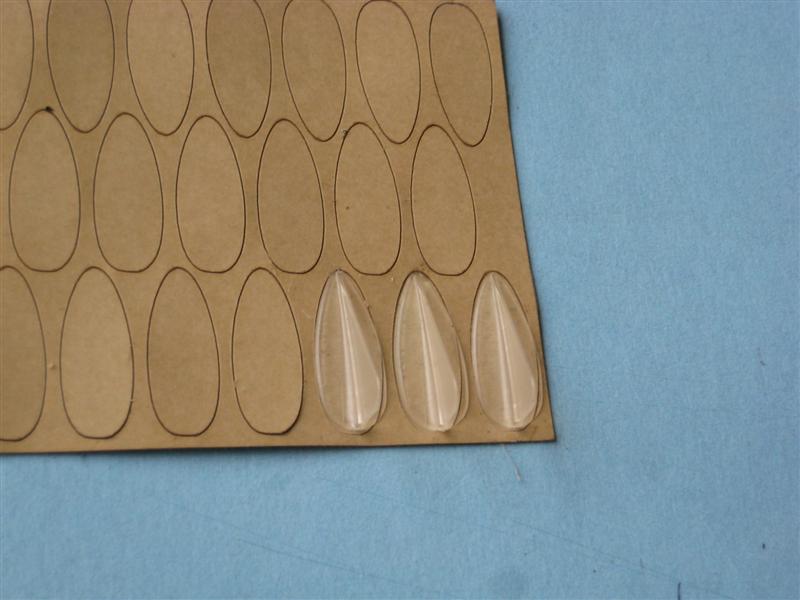
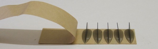
Peel back the shiny-side backing of the strip as you place the VGs side-by-side across the strip, and press them firmly onto the adhesive.
Determining the correct position for the Stolspeed VGs
The VGs need to be positioned such that they have the best ‘bite’ at the airflow when the wing is at the stall angle of attack. If they are too far aft they risk being buried in the thickening boundary layer and the start of separation, so they lose effectiveness at stall. If they are too far forward they are reputed to slightly increase drag at cruise, but I have never been able to meaure such – better to be farther forward than too far aft. So, with the wing positioned at the stall angle of attack, the VGs should be slightly forward of the highest point of the airfoil.
Historically, the margin is considered to be 8-12% of wing chord back from the leading edge to the highest point of the VG, with most experience settling on 10% as the most appropriate. There’s lots of talk around the hangar fliers of finding the ‘sweet spot’, but my experience doesn’t show any dramatic difference at any one point. My testing indicates that 15% can be too far back, so that at a very high angle of attack the VGs can become ineffective. From 8-12% I could detect no difference in stall performance at all, and couldn’t measure any change in drag at cruise speed.
Those figures are to the highest point of the VG, but since it’s easiest to measure to the front tips of the VGs, I recommend starting with the tips at 7% of chord aft of the leading edge – this puts the highest point of the VG at about 9%. We use the measurement to the tips of the VGs to mark the line on the wing because it’s easier to place the VGs accurately to this line. If you try other positions and get significant results with your aircraft, please let us know so that others can benefit.
Preparing the wings
- Wash the wing thoroughly with detergent (not one of those automotive ‘wash-and wax’ products).
- Measure the chord of the wing from the front of the leading edge to the aft edge of the ailerons or flaps. In the case of detached flaperons, measure to the aft edge of the flaperons.
- If the wing is tapered then measure both at the root and the tip.
- Measure from a vertical line extended above the leading edge.
- A carpenter’s level is convenient to establish this vertical.
- Calculate 7% of each the those measurements.
- Measuring from the leading edge again, mark those 7% points on masking tape at the ends of each wing.
- Wipe a zone along that line with alcolhol.
- Stretch a string line tightly over those marks, and secure it with masking tape at a couple of intermediate points.
Placing the VGs on the Wing
- Starting 50mm (2”) from each wing tip:
- Remove the backing from the adhesive on a VG.
- Set the first VG in a notch of the 60mm template with the nose angled out toward the wingtip.
- Carefully touch the very tip of the VG to the wing surface right behind the line.
- Guided by the angle of the template, lightly set the base of the VG onto the wing surface.
Move the template so that the end notch is secured by the last VG already set, and set two more.
Do the remaining portion of the wing with the 90mm spacing template.
120 VGs is enough to do 9.9 metres (32 ft) of wing at this spacing.
If a VG happens to land on a rivet or a seam, displace it just enough to miss the obstacle, then continue the regular spacing.
Placing VGs on the Horizontal Stabilizer
Stretch a line on the underside of the horizontal stabilizer, 100mm (4”) in front of the gap between the stab and the elevator.
Using the 30mm spacing template, set a row of VGs with the front tips along that line, starting from the outside.
If the surface of the horizontal stabilizer is flat, the curved base of the VG will contact only at he tip and the heel. Rub the VG on a piece of sandpaper laid on a flat surface to adjust. Don’t try to completely flatten the base – just make flat areas at the tip and heel, the adhesive will do the rest.
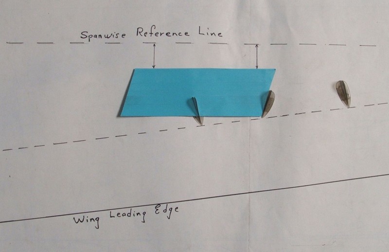
For a Wing with a swept-back leading edge
Since the VGs need to be oriented with respect to the airflow rather than the leading edge, a slightly different procedure is needed with a swept-back leading edge. The VGs are effective at angles from 10º to 20º, so setting them at 15º allows for best margin of variable airflow. There will be very little spanwise flow this far forward, so we can orient the VGs to a reference line at right angles to the centre line of the aircraft.
Snap a chalk line 7% back and parallel to the leading edge as before.
Snap a couple of spanwise reference lines at right angles to the aircraft centre line.
Cut the templates completely across at the end slots.
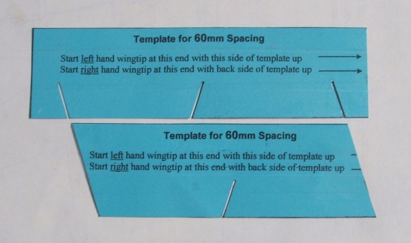
Flip the template over, end for end each time, to match the angle of the previous VG.
If your aircraft will be parked in the sun for much of the time, it’s a good idea to paint the VGs. We have added the maximum UV protectant that is possible, but the thin section and transparency of these VGs will still allow some UV damage.
If you wish to paint your VGs, it is best done before they are installed on the wing and before the adhesive is applied to them. Even on a new aircraft it’s much better to first paint the wing without the VGs on, paint the VGs separately, then stick them on.
Staple a strip of masking tape, sticky side up, onto a length of wood.
Wipe the VGs with alcohol to clean off any release lubricant from the injection molding process.
Place the VGs inline along this tape, so that you can paint both sides easily.
Keep in mind that the VGs are flexible, so you won’t want a thick layer of brittle two-pack paint. Keep the paint layer thin, and without hardener if possible.
Certified Aircraft
Please note that Stolspeed VGs are not approved for certified aircraft.
Note – Be very careful when refuelling wing tanks –Polycarbonate is very tough stuff, but fuel destroys it!
